MGB Kingpin strip
Both garages who have checked the car said something about kingpins, trunnions or wheel bearings. One even commented that he had never seen lower trunnions as bad! They differed over what exactly needed to be done. However, I clearly needed to do something and so I decided to reconcile the two opinions and change everything! I have already described the preparation of a swap hub and swivel axle. Although adequate I 'm not impressed with the brakes and decided to upgrade to drilled slotted discs, Greenstuff pads and braided hoses at the same time. I found an unused set of this lot on Ebay at a discount of nearly £40 although a little rusty.
I jacked up the front of the car using a wooden beam under the suspension member. This could then be supported by axle stands. Sadly I had a real problem here in that the sub-frame was very greasy and oily. As the car is raised the usual occurrence is that the trolley jack will roll to remain under the beam, however, since the cross beam was very greasy the beam started to slip on the sub-frame instead as the car was raised. I tried several approaches to prevent this but even so I had a nasty accident as the beam slipped off completely and the jack impacted the radiator as the car dropped!! There is an obvious dent but I am hoping the seams are OK. It doesn't seem to be leaking but then its not under pressure yet. Time will tell. Be warned that this can happen. I eventually solved the problem by drilling two holes through the beam and inserting bolts so that their heads projected above the beam and could locate in the two holes in the subframe member preventing any possible movement.


Once safely secured I could check kingpin play... frankly there wasn't very much at all on the drivers side but significant play on the passenger side. I decide to start at the drivers... I'm doing both anyway. I could now remove the wheel...
...and identify the two bolts holding the caliper to the disc. These are held by a linked tabbed washer, so tap back the taps and undo the bolts to remove the caliper.
I suspended the caliper with a bungey without straining the flexible pipe.
Once the caliper was off I could check for hub end float... I couldn't find any! Perhaps it had been tightened to try and remove play or perhaps its not so important as the manual might have you believe? I will check that these latest models should have the same float.
Next remove the grease cap from the hub and withdraw the split pin from the the nut.
Removing the nut reveals the tabbed washer and bearing beneath.
The hub pulled off easily. The rear oil seal wasn't in great condition
... but there was no sign of leaking onto the brake back plate.
Remove the four bolts to release the back plate, mine was rusty and I wanted to repaint.
The disc is held on to the hub by 4 nuts and bolts- easily removed with an impact wrench. Its not usually necessary to remove these but as I was intending to swap the discs so I needed the bolts!
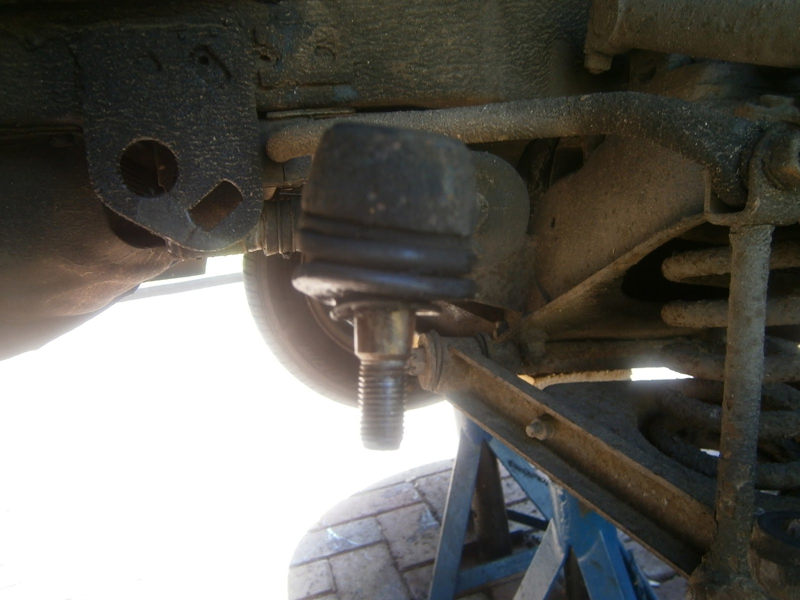
Returning to the car I separated the track rod end ball joint using a separator. The boot on this end didn't look very good and I will replace the cover at least.
I removed the steering arm from the swivel axle by undoing the two bolts and washers.
The next step was to remove the kingpin, but before this can be done the spring pressure must be relieved so I put a trolley jack under the spring seat and raised it until the arm was moved up and the spring compressed. The large captive nut at the top of the kingpin can then be removed, although the king pin can't drop down until the upper trunnion bolt is removed as this passes through a cut-out in the king pin. Consequently, the next step is to remove the split pin and undo the upper trunnion bolt which could then be tapped carefully back through releasing the top end of the king pin.

This released the king pin upper end allowing the pin and stub axle to fold down pivoting on the lower trunnion.


I removed the lower trunnion bolts (split pin again) and tapped the lower trunnion bolt out releasing the king pin still with the upper trunnion assembled on the top.
 |
| King pin removed |
The lower arms were worn out of round where the lower trunnion bolt passes through them and this could account for some of the wear observed by the garage inspections, so I obtained new lower arms to replace them. This means recovering the spring seat which is held between the arms by two bolts each side. However, on the forward side one of these bolt fastenings is substituted by the drop link from the anti-roll bar visible above. I removed the nut securing the antiroll bar link inside the arm and also that securing the second nut on the same side. However the arm cannot be removed until its detached at the top end. To release it here I had to undo the two bolts securing the inner arm bushes (split pins here too)
 |
| Castellated nut plus split pin securing inner bushes of the lower suspension arm. There are two of these so I removed both. Note the thick washer beneath the nut and compressing the inner bushes. |
The forward arm could then be tapped forwards off the fulcrum bolt
 |
| Inner bushes lower suspension arm- nut removed and arm being tapped forwards- leftwards in this picture. |
... and releasing the arm from the spring seat as came away
 |
| arm coming away from spring seat |

9
The spring seat was released from the rear arm by unscrewing the two bolts that hold it on that side. The seat and brake back plate were then cleaned up in preparation for anti-rust treatment and painting.
Reassembly
I carefully cleaned any remaining swarf from the new bushes- including all the nipple holes and O ring grooves. This was surprisingly difficult! Place the square section dust seal sealing ring in the inside (i.e. top) of the lower bush
and the round section O ring (water seal) on the bottom of the kingpin

Insert the dust shield making sure its seated properly at top and bottom and the two sprung sections are free to slide.
Insert the king pin- grease the contact sections
Assemble the top trunnion bushes to make sure they slip easily into the top trunnion- make sure to remove any obvious internal corrosion to make sure that they can
I've been soaking the upper thrust washers in oil to make sure that any oil impregnation is up to the mark
I assembled the thrust washers into the base of the upper trunnion, the oilite thrust against the trunnion and steel thrust washers beneath and nip up the top nut. This is a nyloc nut that has limited reuse so I didn't use the new nut at this stage but one of the old ones having removed the nyloc insert so that it could be used conveniently.

Align the crescent cut out in the king pin with the trunnion and reinsert the rubber bushes before nipping up the top nut hand tight. There is a confusing section in the manual about setting the king pin rotation and it took me a while to get my head round it. However the important point is that the position of the upper trunnion (and thus the nut above it), is actually fixed on the king pin by the bush/bolt assembly of the upper pivot bolt passing through the crescent cutout. This means that the stub axle is free to slide up and down the king pin between the two trunnions. The idea is to add shim washers under the base of the upper trunnion (below the oilite thrust washer) to exactly take up this movement. Too few shims and the up-down movement will be excessive (i.e. more than 2 thou), too few shims and the stub axle will bind making rotation around the kingpin too stiff; it should rotate freely on finger pressure. In order to assess this movement the top nut needs to be tightened to 60 ftlb with the upper link pivot bolt inserted. However you can estimate the range needed simply enough with hand tension. I found that using three shim washers led to excessive stiffness in rotation even when tightened only to hand tension- this is clearly too much. The hand-tight test gave satisfactory results (free rotation and no end float) at 2 shim washers so this has to be close. Under full nut torque this may still prove to be too much shimming, but I have a set of fine adjustment shims and can test/fine tune the adjustment under full nut torque in the car. I put the assembly aside to sort out the hub/disc.

I refitted the lower suspension arm- firstly cleaning up the inner arm mounting points and applying a smear of corrosion block (rubber friendly) grease here.
I could then insert the lower arm inner bushes and fit the new lower arms and spring pan. The lower arms are not identical- the forward arm has a reinforcing pad for the ARB drop link stud*; I should have fed the ARB drop link arm in as well but it can be inserted later.
*I do wonder why there is no such reinforcement for the fulcrum bolt itself. Its seems that wear resulting in ovality of the fulcrum pin holes is common and was certainly evident in my case.
 |
| Repainted spring seat- fitted with new lower arms. |
At this time I also noticed that oil was leaking from the driver's side gaiter and since this was looking a little bit tatty I decided its probably a good idea to change the gaiters as well as the track rod end boot now, whilst I have the front stripped down. I ordered the necessary parts.
I refitted the ARB drop link
Its known to be very tricky to get the top trunnion with new bushes between the shock absorber arms. Luckily these can be spread as one of them (the rear here) is detachable. So remove the arm pinch bolt.
The arm is held on with a bolt through the pivot- this runs in a crescent cut-out in the shock absorber shaft; so to remove the arm you need to remove the bolt fully. I cleaned up the shock absorber shaft and applied corrosion block grease before rebuilding.
 |
| loosening the shocker arm retaining bolt |
I assembled the thrust washer seal pack for each side, fit the seal support into the wide end of the seal and slip the thrust washer inside


Ensure the spacer tube is installed in the lower trunnion (I needed to ream one of the trunnion bushes to get a decent sliding fit) and then clip the seal assemblies onto each side. Slip the whole assembly between the lower wishbone arms. Feed the bolt through towards the front of the car and secure with the spring washer and castellated nut. This needs to be torqued down to 45 lbft*. In my case this sounded a bit of a warning because the castellations were then wound down well below the hole in the bolt!! I assume that some packing/shimming is needed.
* The 45 lbft figure came from another forum but is probably wrong and should be closer to 75 ftlbs.
 |
| nut castellations are well below the hole in the bolt and will not help to anchor it in this position. |
Fold up the king pin and fit the top trunnion with its bushes and upper fulcrum bolt. Obviously this will eventually need the spring re-installed, but the spring has no influence on the shimming of the upper trunnion- it just makes all the removal and testing harder, so I assembled it first of all without the spring. I could then torque down my "old" top kingpin nut and check the turning friction and end float- I found as I had suspected, that the swivel axle was now too stiff to turn so I assumed the two washers I had fitted were too thick. I removed the top trunnion and extracted the pair of thrust washers. These were 115 thou in thickness. I rearranged the various washers I had- not a great choice- but got a pair reducing the total thickness by 4 thou. I reassembled the top trunnion and checked clearance float and swivel axle rotation- result! No clearance but free and easy rotation!

Accordingly I dis-assembled everything and then put it back together installing the road spring and raising the lower arm with a jack to compress it and allow me to re-fit the top trunnion and shock absorber pinch bolt. This was very awkward as its hard to get the spring back in and if I was doing this again I think I would delay fitting the ARB drop link until after inserting the spring- fitting the link whilst the spring is being compressed. I used corrosion block on both shocker pinch bolts and upper fulcrum bolt.
 |
| King pin installed with spring on wishbone |
However, having installed the kingpin it was clear that the castellations on the fulcrum bolt nut still did not correspond with the fulcrum bolt holes when torqued down. This caused me a lot of concern but I now attribute it to the somewhat puny and thinner thrust washers supplied with the new fulcrum bolt kit, and the nut itself being 2mm narrower than the original.
 |
| Castellations and bolt pin hole ... no correspondence |
Accordingly I relieved the spring pressure and removed the bolt again and packed under the bolt head with flat washers to draw the bolt hole towards the castellations. I could then fit the split pin and fold it to secure.
 |
| ... correspondence! Using old nut and washer sunder bolt head. |
It was now very hard to tighten the ARB drop link bolt and this had suffered some thread damage so I removed the drop link completely to chase the threads (7/16 20 tpi) with a die to restore them.
This allowed me to refit the drop link and torque it to 60ftlb as required.
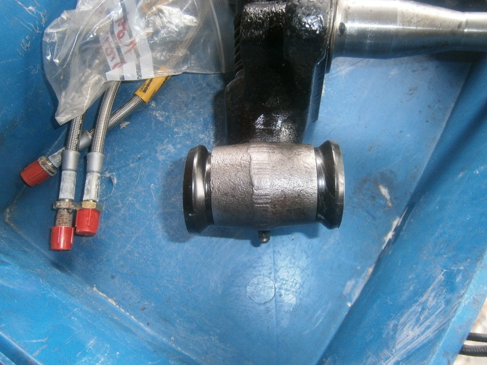
MGB Brake upgrade- changing the pads for greenstuff
The brake hoses use a variety of nut sizes, 1/2AF; 5/16 W/W and 13 or 14mm. I applied plenty of penetrating fluid and released the metal pipe union above the flexible hose. This immediately started dripping fluid and although I will renew the fluid entirely I don't want uncontrolled leakage or the possible introduction of air locks so...
I sealed the union with a nipple cover. I could then unscrew the nut holding the flexible hose to the mounting bracket whilst holding the hex section on the end of the hose itself.
The caliper was already unscrewed from the stub axle. The pads showed some evidence of uneven wear but I'm not sure how significant this is. I will need to retract the pistons to fit the new pads so this should show whether one of them is stiff or seized.
At their top the pads are secured with a split pin and spring clip at each side
I straightened the pins and removed them


The pads could then be lifted out

Which revealed a fairly messy caliper that I cleaned up by brushing in brake cleaner.
The new pads have an anti-squeal patch backing which needs to be cut to shape...
... and stuck to the back of the pads. It needs to cover all those parts which contact the piston
I had a bit of difficulty in pushing the pads back but using a Girling pad lever I eventually succeeded. Some sort of screw clamp would be better for this. I inserted the new pads and retained them with new spring clips and pins - here just before the ends were bent over..
I removed the old flexible hose

and fitted the new hose using the fresh crush washer on the caliper union

The hose could then be reattached to the metal pipe in the car, hanging it once more from a bungey to prevent strain on the new hose, I will refit it to the brake disc when the new disc has been installed.
MGB Refitting the hub and upgrading to a slotted disc
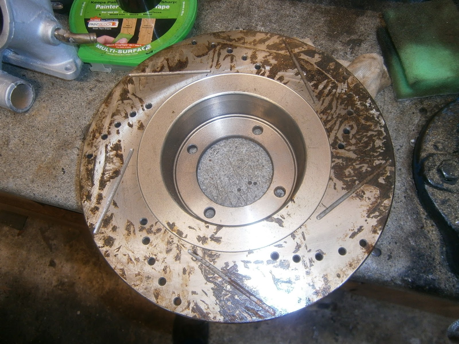
I had obtained new slotted and drilled discs with
Greenstuff pads from Ebay; unused but left over from an abortive restoration. I fitted the discs to the hubs with the 4 bolts. The discs had some surface rust from storage. I'm confident that this would wear off rapidly in use, but the rust particles released would cause more rapid pad and disc wear so I removed the rust with rust removing gel.
Rust removing gel applied.
Cleaned disc attached to hub and torqued to the correct tightness.
 |
| Disc cleaned up and fitted to the hub. |
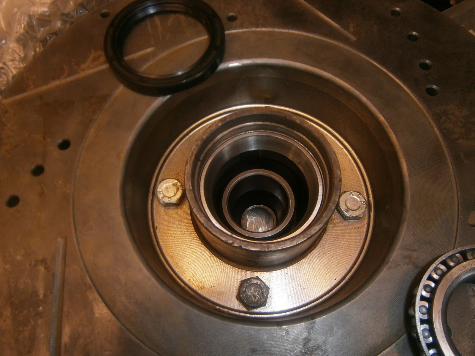
I had already determined the approximate shimming needed to give a 2-4thou end float on the hub when torqued between 40-70 ftlbs. I assembled the hub and tested again in -position (I had still not yet greased the bearings or fitted the oil seal)
This was appx right, but I did need to repeat the shimming to be sure. The basic approach is to over shim, tighten the axle until until the holes coincide with the castellations between 40- 70 ftlbs. Then measure the end float, remove the hub and reduce the shim stack so as to leave a 4 thou end-float, (refit the shims you have removed above the hub where they will pack the nut out to its previous position) tighten down and recheck. When correct I could finalise the hub assembly and fit it again so first I greased the large bearing using the grease supplied in the kit. I pushed the grease into the bearing wide groove until it passed though and emerged from between the rollers. Drop in the internal hub spacer tube...

Followed by the large inner bearing
and tap the oil seal into place above it. I could then grease the outer bearing and refit it with the shim stack underneath before adding the tabbed washer and hub nut. I tightened until the holes coincided at a suitable torque and then rechecked endfloat. Luckily all good, so I fitted a new split pin and the grease cap containing a reservoir of extra grease.
I refitted the steering arm...
Followed by the brake caliper.
MGB Track rod end reboot/replace steering rack gaiter replacement
This is a dirty job owing to the accumulated grease and muck on the bottom of the car. However when I started the king pin job it seemed to me that the gaiter had been leaking for a while- the track rod end was heavily encrusted in oily muck and leakage around the gaiter was evident.
Although I couldn't find a split in the gaiter it could well be hidden. There was also a nick in the rod end boot. Both of these things suggested it was time for an overhaul and as gaiters are fairly cheap I decided to change those too!
First step- clean up what you can!
Secondly remove the track rod end. I held the lock nut and unscrewed the rod end with an adjustable wrench-

it came off easily enough, I was careful not to unscrew the lock nut at all. It was actually pretty tight on the rod. I cleaned up the thread as best I could.
Then I marked the last ridge of thread visible in front of the lock nut with a red sharpie before unscrewing the lock nut. I held the rod in a molegrip using a scotchbrite pad for grip and to avoid damage.

The red marking doesn't show up very well in the picture- but honestly, its really there! Enlarge the pic to check.
I hadnt seen any play in the ball joint and I have some replacement boots anyway so I'll try just changing the boot and swap the joint if it doesn't work.
First step is to carefully remove the spring tie that holds the old boot on. New boots don't usually come with clips and I don't like using snap ties on them because their sharp edges dig into the rubber.
Carefully levering up the spring tie
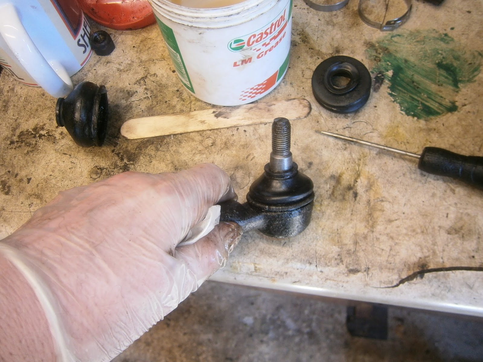
Ease the boot off to reveal the ball joint. Although I could see the beginnings of some rust here there was definitely no play. I have a choice of 2 sizes of joint boot- old boot top, two new ones below that and the spring clip below them. The joint appears to be between these sizes but the smaller one will fit.
I scraped out much of the old grease and cleaned up the joint before repacking it with fresh Castrol LM grease
I find that the boots are easier to fit if you turn them inside out first, slip them over the rod and then unfurl them over the joint. This way the boot flips over the ridge in the ball joint base.

It fitted well. Finally I eased the spring clip into position to hold on the new boot and this one is ready to go back on, but before I can do that I need to sort out the gaiters.
Removing the gaiters
The gaiters are held on by two screw clips- ideally, nylon ratchet ties aren't as good as you can't get them as tight and they can cut into the rubber. I Unscrewed the smaller clip first. This should release the oil from the rack but in my case virtually none came out as most had leaked away! I will refill when I have done the second gaiter.
I think this also showed me what the problem had been in the past because the clip wouldn't unscrew- the nut just span and the PO had rammed a plastic cap on the screw to keep the clip on. However this didn't allow any real tension to be generated on the clip and I think this end of the gaiter was always leaky!

I removed the inner clip and the old gaiter- I couldn't find any splits or holes in it and I think the problem was that poor clip! However, I've got new and so I'll use those.
Fit the new gaiter and...
slip on the clips
I fitted the new gaiter with new clips both sides- these do tighten up- however don't tighten the outer clip (small one) until you have aligned the the track rod end and steering arm.- I found I needed to rotate the rod and had to slacken the gaiter clip to avoid twisting it.
I fitted the track rod end lock nut to its original position (note the red on the thread)
... and then screwed on the new booted track rod end until it jammed on the lock nut. I then tightened both together- this should be close to the original alignment but I will get the wheel alignment checked again when I have done the other side. Track rod end does end up very close to the brake back plate.
This completes this side of the car although mentally I need to remember that I still need to peen over the ends of the caliper double-tab washer, put grease in the kingpins and oil in the rack - no point in this last job until I have swapped the gaiter on the other side.
The other side strip went as before- except I was much faster- a few pics for reference.
  |
| Lower trunnion fulcrum bolt- only just locating the split pin in the castellations ! |
 |
| Grease cap and caliper off |
 |
| Hub and backplate off |
 |
| Lower trunnion not looking too great- certainly a lot of play this side! |
 |
| Disconnected ball joint. No splits visible but I decided to change it as before anyway. |
 |
| Remove nut and washer from ARB drop link and remove link before removing the lower fulcrum and lowering the spring. |
I reassembled the calipers with the Greenstuff pads as before. I also changed the gaiter- there was no sign of oil leakage this side and the clip was tight. However it still bore the little plastic thread protector so I now think that this wasn't a PO bodge but a genuine component intended to protect the gaiter from the screw on the clip- I will replace these both sides.
I removed, cleaned and painted the the brake back plate and spring seat before reassembly as before. Not bad for a half day- I will try to reassembled tackling the various shimming issues tomorrow!