Reconditioning the Master cylinder using repair kit Lockheed GRK 1004 (Delphi LK11217)
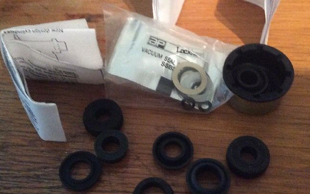
My brakes have always been spongy- I had expected the braided hoses to improve the firmness of the pedal but no such luck. I have checked the system and can find no leaks, and I've bled a couple of litres of new brake fluid through but still a spongy pedal. I'm now thinking it must be the master cylinder so the next thing to try is to change the seals. I bought a Lockheed Girling kit (original rather than an after market version, because I wanted the instruction leaflet. Getting the seals in the right positions and the right way round is essential so these diagrams are a great help. The kit also includes new "O" rings for the pressure differential warning system- and as mine doesn't work this is another reason for the overhaul. The kit cost a little more than the others but the instructions are invaluable and cover both the working pistons and the pressure warning system.


The kit is comprehensive... it includes parts for different versions of the same cylinder in different applications. This should really be explained more clearly but I think you are expected to know which bits to put in from the bits you take out! The kit includes the boot, cover and nylon washer for the rear of the master cylinder, 7 seals and a bag containing a new copper washer for the brake fluid warning system, 2 sets of "O" rings for same and 2 metal cylinder washers for the pistons. It doesn't include a new circlip or secondary piston retaining pin.
The kit will deal with two versions of cylinder and two versions of the low fluid warning system.
Seals:
There are two doughnut seals which fit into top of the MC below the fluid reservoir. These are self explanatory and nothing else looks like them. There is also a top hat seal which I think is intended for a different reservoir.
The rest of the seals look the same so I measured their thickness to help identify them (values in inches)
0.389 and 0.212; Alternatives for secondary cup seal (rear of rear piston)
0.187 x2 Main cup seals fitting to the front of both pistons over the metal washers
0.137 Reverse cup washer fitting to rear of the front piston.
There are two pairs of "O" rings for the warning system- one small and one large. These posed a problem (see on).
Stripping the tandem master cylinder
 |
| Master cylinder- three fluid pipes and two nuts holding it to servo. RHS nut is easy to get at (1/2"AF spanner) but LHS is awkward. Don't forget to disconnect the wiring for the warning switch. |
 |
| You can manage with a flat ring but a 1/4" drive socket on a double extension is easier. |
|
 |
I could suck out the fluid in the rear section with a vac bleeder but couldn't get at the forward reservoir- so remove the fluid unions and catch the draining fluid- note the disconnected line has been sealed with a bleed nipple cover.
|
 |
I plugged the lines with bleed nipples to prevent dripping fluid which can damage the paintwork (and apparently has in the past!)
|
 |
| BMC on bench, remove the two screws holding the reservoir on |
 |
| ...and pull the reservoir out of the doughnut seals. |
 |
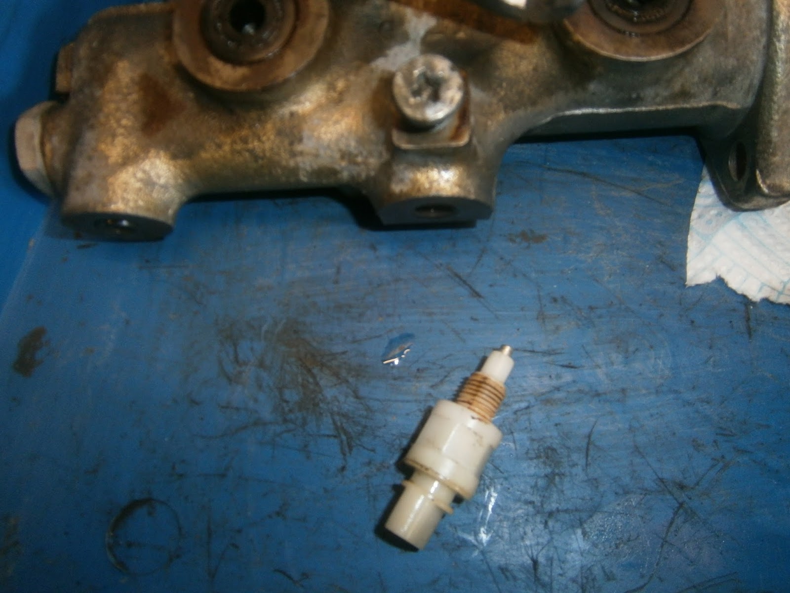
| Unscrew the warning switch from the base. Fair bit of crud in the threads but my switch has not worked since I had the car. This might be sealing compound as fluid can leak from this switch if the seals on the pressure warning piston have been damaged. |
 |
| crud/compound also inside the switch bore. A cross bar visible at the bottom is the activation ridge of the pressure differential piston and this is in the correct position. |
 |
| Remove the rear piston by compressing the circlip with appropriate pliers, the rear piston will pop out under spring pressure when the clip is removed. |
 |
| Circlip- not in kit so save it. |
 |
| Pulling the rear piston out- fluid will also come out so drain it carefully. |
 |
| The spring will also come out next (it just tips out) It has a washer on its rearward end that protects the front seal on the rear piston |
 |
| washer on spring goes against the forward seal |
 |
| Lever out the front doughnut seal to reveal the secondary piston retaining pin beneath |
 |
| Use a rod to push the front piston inwards which relieves the tension on the retaining pin which can then be lifted out with some snipe nosed pliers. This pin is also not included in the kit. |
 |
| Once the pin is out the front piston will slide out... |
 |
| ... followed by the black spring- note there is a washer on the rear of this spring again to protect the seal on the front of the piston. This completes the stripping of the hydraulics. |
Stripping the low pressure/fluid warning system
 |
| Hold the BMC in a soft-jawed vice |
 |
| ... and unscrew the cap nut (13/16 AF) |
 |
| The cap nut has a pronged extension on it. |
 |
| The warning piston should just tap out- mine was stuck fast which probably explains why it didn't work. I managed to move it a little by using a punch to tap it inwards and then levering through the switch hole on the activation ridge visible in the base. Once a little movement had been established it could be pulled out with a small pair of pliers. |
This is where problems arose. The instructions detail two types of warning piston- I was expecting that mine would be the later type as this is one of the last MGBs made, and I expected to find two O rings and a plastic spacer as the information suggested. The trouble is that once removed, my piston didn't look like either of the two forms shown, there was only one O ring and no plastic spacer!
My piston has an extra ridge in the centre- the thin ring-like projection that I am calling the activation ridge and it was this that was visible though the switch hole above. There are obvious channels either side of this ridge instead of the single channel visible in both types illustrated. I think this makes my piston longer than both of those forms and could explain why I found no plastic spacer in the bore. However the piston should presumably have had 2 "O" rings and only one was present.
 |
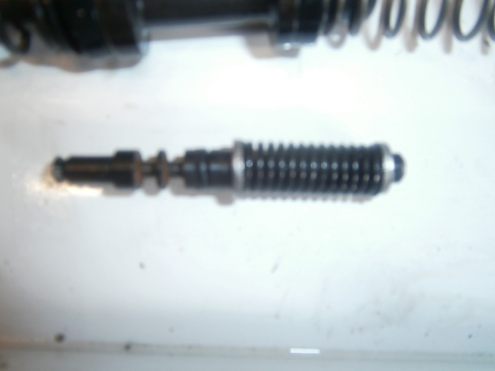
| Brake fluid low pressure warning piston as removed (front towards left). Note only one O ring and the prominent central ring section (activation ridge) which formed the cross bar visible at the base of the switch hole and the two channels immediately beside it. |
 |
| Pistons showing their fit with springs (front is left). Warning cylinder below (front is right) with its single "O" ring in position |
 |
Positioning of seals on rear piston, both seals (open faces)
face forwards. |
 |
| Position of seals of front piston- forward seal faces forward, rear seal faces rearwards |
 |
Only 1 O ring on warning piston (central).
Note activation ridge on the left with obvious grooves on both sides. This lengthens the central portion compared to the pistons illustrated in the instructions.
|
|
Fitting new parts; seals and "O" rings
Stripping the seals is relatively straightforward BUT you absolutely must keep the old ones separate from the new. This will be awkward because you will want to compare them to be sure of their positioning and that you are fitting like-for-like, but it is essential to keep it clear in your mind which are old and which new. I may have become confused and refitted at least one old seal! Lubricate well with fresh brake fluid or the assembly grease provided as you fit them. Don't forget to change the metal washers under the main cup seals on the front of both pistons.
Fluid warning piston
The warning system piston was a problem for me- it appeared to lack one "O" ring and the plastic spacer. It was also functionless, gummed solid inside the cylinder. As it didnt match either of those illustrated I wasnt sure wich O rings should be used to reassemble. I dismantled the pressure differential piston completely- although I suspect this isn't really necessary. Here it is with the 2 C clips that retain the spring, the single O ring removed and the new one installed. Note that the ring I removed appeared to be of the larger size so I fitted a large one to replace it.

However assembled this way the piston would not slide back into the bore fully and the activation ridge was left to far forward of the switch hole. I did wonder if this was due to the remnants of an old O ring blocking the bore, but careful probing revealed nothing.
 |
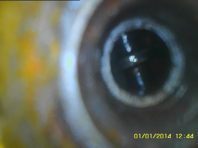
| Borescope looking down piston bore from the front cap nut opening, no obvious obstructions |
 |
| Incorrect fitting of piston- the shoulder is visible through the switch hole not the activation ridge. |
 |
| Using the smaller rings the piston slipped in farther and the activation ridge now aligned with the switch hole. |
- I swapped the rings for two small ones and the piston now slid in easily and adopted the right position. I suspect the o rings stretch during fitting/use and so the ring I removed misleadingly resembled the larger size.
 |
| Pressure differential piston reassembled |
Although I could fit the brake piston seals with my fingers, I had to use the point of a scriber to ease the front ring into place. The rear ring is loaded into a retaining V groove at the back of the piston (extreme right in the pic above)- it rolls into its final position as you push the piston into place. Presumably it also rolls off again when the piston is removed which may be why I didn't recover it. I refitted the cap nut with its new copper washer.
Master cylinder
Assembly is as they say the reverse of stripping. Drop in the black spring (washer uppermost)
Followed by the front piston- nose forward so it fits inside the washer and spring. You then need to compress the piston onto the spring by pushing it against a rod held in a vice until you can refit the retaining pin to hold it compressed.
Refit the centre spring and rear piston, press it in and retain with the circlip. You can then insert the new doughnut seals and refit the reservoir.
The rear of the cylinder as I removed it was open and revealed the circlip retaining the pistons. During my machinations with the pressure piston I did fit and remove the mc a few times. I found on one of these that the mc came away with an additional cap at its rear. I am not sure whether this is a part of the servo or the master cylinder but these parts are included in the kit and so I renewed them as well.
 |
| Cap on end of MC |
 |
| Metal cover pulls off and the rubber boot beneath simply pulls off as well. |
 |
| Fitting a new boot |
 |
| Place the nylon profiled washer/bush inside the metal cap to prevent the pushrod from chafing |
 |
| and slip the cover over the new boot. |
I have read in several accounts just how important bench bleeding the cylinder is for proper function. I suspect that this is probably what was wrong with my system. In the US they sell really nice, cheap little kits of plastic bungs and tubing just for this purpose. Although they cost less than $3 in the States, postage to the UK is well over $20 so obviously not worthwhile. I made a bench bleeding system using three M10 1.0 unions and three bits of flared brake tubing.
I could then fit some clear tubing from the brake pipe to the reservoir, fill the latter with fluid and pump the piston by pushing it back onto a rod held in the viceuntil no more bubbles came through the tubes..
A word of warning though if you do decide to do it this way... the pistons can only displace so much fluid. This means that the volume of brake pipe plus clear hose must be lower than that volume or the bubbles are simply moved back and forward along the hose. You need short enough hoses that the bubbles are actually expelled into the fluid reservoir. One good sign was that there was no leakage through the pressure differential switch hole so the "O" rings I chose must seal- at least at low pressure.
Once that was achieved I could refit the MC leaving the bench bleeding connections in place. These were removed only when I was ready to reattach the brake pipes. Finally the system needs a good bleed- which I will do later- but I didn't lose much fluid in the installation because the bench bleeding pipes were in place and capping the disconnected brake pipes prevented loss there. Consequently I don't think there is a lot of air in the system and surprisingly the pedal is already much firmer!
Operation of the low fluid pressure warning system
The pressure differential warning system is in principle simple- the realization of these principles produces a piston that certainly isn't simple.
The basic idea is that a shuttle piston is installed in the bmc that is free to slide forwards and backwards. The piston is exposed to pressure in the rear circuit at the front and pressure in the front circuit at the rear. Provided the braking system is working fine then these two pressure will be equal and the piston will remain in position. However if you loose fluid in one circuit brake fluid pressure in that side will fall, pressure in the remaining circuit is still high and so this pushes the piston forward or backward depending on which circuit has failed. The piston is designed with a prominent ridge. When both pressures are in balance the ridge is centrally located in the switch bore and was visible here when I stripped the mc.
 |
activation ridge on piston visible at the bottom of the switch bore.
|
The warning switch has a spring loaded plunger. When the plunger is depressed the contact is broken and the switch is "off". If all is well this plunger will make contact with the activation ridge of the piston positioned as above. This will depress the plunger and so deactivate the warning light. If however the piston moves in either direction, the switch plunger will slip off the activation ridge and pop out into whichever channel is now exposed. This closes the circuit and activates the warning light. The extended plunger also now locks the piston in that position. This means that the light will remain on until serviced. In some cases (I'm not sure if that applies to the MGB) the piston is also described as a shuttle piston. It acts to isolate the two braking compartments as it slides so that all effort is devoted to the circuit that is still working. If so then running the car with an incorrectly positioned piston could mean that only half the brakes are working properly?
This reasoning suggests that the switch was correctly located in my bmc, but as it was stuck firmly, it couldn't move and activate the warning lamp whatever happened to the pressures. To complete the job I did test the switch itself and found it was also inoperative so I will need to replace this switch too. Its surprisingly expensive but I will order and fit one. It don't think its easily tested but I wouldn't want an MOT failure for such an easily swapped item.